What Is a Variable Frequency Converter and How Does It Work?
A Variable Frequency Converter controls an AC motor by changing the frequency and voltage of its electrical supply. Rather than running at one fixed speed, a motor can then adjust to changing process demands. Picture a conveyor slowing as products move toward a packing station, or a pump easing its output when less water is needed. These adjustments can improve control and may reduce energy use in suitable applications.
Inside the converter, incoming AC power is typically rectified into DC. A DC link smooths and stores that energy briefly. An inverter then switches the DC into an AC output with a controlled frequency and voltage, often using pulse-width modulation. The details vary by design, but the basic sequence is consistent. That distinction matters. Frequency helps set motor speed, while voltage and current affect torque and heating. A converter is not simply a speed dial: motor type, load, cooling, wiring, and parameter settings all influence performance. In practice, poor setup can cause nuisance trips or stress equipment, even when the displayed speed looks reasonable. This guide explains the main components, the conversion process, and what to consider when choosing a unit. It also looks at practical limits, because a variable-speed drive cannot fix every mechanical or electrical problem. The useful question is not only how it works, but whether it suits the motor and the job.
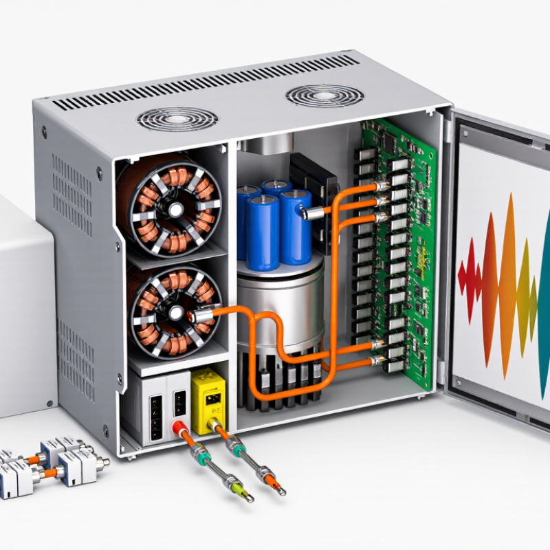
Definition and Purpose of a Variable Frequency Converter
A variable frequency converter is an electronic device that changes the frequency and voltage supplied to an AC motor. Many units convert incoming AC power to DC, then use an inverter to create AC output at a controlled frequency. The motor’s speed generally follows that output frequency, though its design and load also matter. In practical terms, a pump motor can run more slowly when water demand falls, rather than operating at full speed all day. Less speed can mean lower energy use and gentler starts. Not magic.
The converter’s purpose is to give operators adjustable motor control. It can help regulate a fan, pump, conveyor, or other driven equipment, while limiting abrupt starting currents and mechanical stress. A control panel may set a target speed, or a sensor may adjust it as pressure changes in a pipe. Frequency and voltage need suitable coordination to maintain motor performance. At low speeds, a motor’s own cooling fan may move less air, so prolonged operation can require extra care. Electrical noise and system compatibility deserve attention too. A converter is not a universal efficiency fix; choosing one requires matching it to the motor, load, and operating conditions.
Main Components and Their Functions
A variable frequency converter controls an AC motor’s speed by changing the frequency and voltage of its electrical supply. Its rectifier converts incoming AC power into DC. The DC bus, with capacitors and sometimes inductors, smooths and stores that power. Then the inverter switches the DC into adjustable-frequency AC. That is the basic energy path.
A controller sets the output frequency and coordinates switching. Sensors can monitor current, voltage, temperature, or motor speed, while protection circuits respond to overloads and overheating. Cooling matters, too: a blocked vent can raise internal temperatures even when the motor runs normally.
The International Energy Agency’s 2011 report, Energy-Efficiency Policy Opportunities for Electric Motor-Driven Systems, estimates that motor-driven systems use about 45% of global electricity.
That figure gives the converter’s role useful context, but it does not mean every installation will achieve the same savings. With centrifugal pumps and fans, reducing speed can sharply reduce power demand; the U.S. Department of Energy describes this relationship through affinity laws.
In practice, incorrect settings or poor system matching can erase some benefits. A converter is not a magic box.
How the Converter Changes Input Power
A variable frequency converter changes fixed-frequency AC into adjustable-frequency power for an AC motor. Inside, a rectifier converts incoming AC to DC. Capacitors smooth the DC on an intermediate bus. An inverter then switches it into a new AC waveform, adjusting frequency and voltage through pulse-width modulation. Lower frequency slows the motor’s rotating magnetic field and usually reduces shaft speed.
The International Energy Agency’s 2011 report, Energy-Efficiency Policy Opportunities for Electric Motor-Driven Systems, estimates that motor-driven systems use about 45% of global electricity. This figure describes a broad category, not the savings from any single converter. When a fan or pump runs below full speed, lower flow demand can reduce power use. The outcome depends on the load, settings, and operating hours. A converter does not save energy by itself. There is a catch. Real installations can be messier: harmonics, motor heating, and poor settings need attention.
Tips: Match the converter’s current and voltage ratings to the motor. Set its minimum and maximum frequencies carefully. Check cooling at low speed, especially with a standard fan-cooled motor. Record power use before and after adjustment; lower speed alone does not prove lower energy use.
How a Variable Frequency Converter Changes Input Power
A converter rectifies fixed-frequency AC into a DC link, then uses an inverter to produce AC at a controllable frequency. This chart shows a simplified 480 V, 60 Hz motor V/f profile: voltage rises with frequency up to the motor’s base frequency, then remains limited.
Values are illustrative line-to-line RMS fundamental-voltage references. The inverter’s switched PWM output is not a pure sine wave; motor inductance smooths the resulting current.
How Output Frequency Controls Motor Speed
What Is a Variable Frequency Converter and How Does It Work?
A variable frequency converter changes the electrical frequency supplied to an AC motor. The motor’s speed generally follows that frequency. A lower frequency usually means slower rotation; a higher frequency usually means faster rotation. The relationship is useful, though not perfectly tidy.
For an induction motor, synchronous speed depends on frequency and the number of magnetic poles. For example, reducing a 60-hertz supply to 30 hertz roughly halves the synchronous speed. The rotor runs slightly below that speed because of slip. The converter also adjusts voltage as frequency changes, helping maintain magnetic flux. At very low speeds, however, a motor’s own fan may cool it less effectively.
In a workshop, lowering frequency can help a conveyor start gently and move materials at a controlled pace. Raising it can increase output, but only within the motor and machine’s ratings. Frequency alone does not guarantee safe operation. Load, temperature, and acceleration settings matter too. Real installations can be messier than the basic explanation suggests.
Tips: Check the motor’s nameplate and speed limits before changing settings. Watch for excess heat or vibration, especially during extended low-speed operation.
What Is a Variable Frequency Converter and How Does It Work? - How Output Frequency Controls Motor Speed
| Output Frequency | 2-Pole Motor
Synchronous Speed | 4-Pole Motor
Synchronous Speed | 6-Pole Motor
Synchronous Speed | How the Frequency Affects Operation |
| 5 Hz | 300 rpm | 150 rpm | 100 rpm | Very low synchronous speed; cooling and available motor torque may require attention. |
| 10 Hz | 600 rpm | 300 rpm | 200 rpm | Low-speed operation; a standard shaft-mounted fan also turns slowly. |
| 20 Hz | 1,200 rpm | 600 rpm | 400 rpm | Reducing frequency lowers the rotating magnetic field speed and the motor’s synchronous speed. |
| 30 Hz | 1,800 rpm | 900 rpm | 600 rpm | At half of a 60 Hz reference frequency, synchronous speed is also half the 60 Hz value. |
| 40 Hz | 2,400 rpm | 1,200 rpm | 800 rpm | Increasing frequency raises synchronous speed; an induction motor’s loaded speed remains slightly lower. |
| 50 Hz | 3,000 rpm | 1,500 rpm | 1,000 rpm | Common supply frequency in many regions; rated motor voltage and frequency should be observed. |
| 60 Hz | 3,600 rpm | 1,800 rpm | 1,200 rpm | Common supply frequency in many regions; operation above a motor’s rated frequency may reduce available torque. |
How a variable frequency drive works: It converts incoming AC power to DC, then switches that DC to produce AC output at a controlled frequency and voltage. Changing output frequency changes the speed of the magnetic field in the motor.
Synchronous speed formula: Speed (rpm) = 120 × frequency (Hz) ÷ number of motor poles. The table shows synchronous speeds; a loaded induction motor typically runs somewhat below synchronous speed because of slip.
Important: Actual operating speed and torque depend on motor design, load, drive settings, cooling, and the motor’s rated voltage and frequency.
Common Types and Applications of Variable Frequency Converters
Variable frequency converters are commonly grouped by the way they change electrical power. The most widely used type is the voltage-source inverter drive. It converts incoming AC power to DC, then switches that power back into AC at a controlled frequency. Pulse-width modulation helps shape the output. In many systems, this also allows motor speed to follow changing demand.
Other designs suit different power conditions. Current-source inverters regulate output current and are often used in larger industrial installations. Cycloconverters convert AC directly to lower-frequency AC, though they are less common in everyday equipment. Some converters accept single-phase input and provide three-phase output, which can help operate a suitable motor where three-phase supply is unavailable. Compatibility still matters. Check the motor’s voltage, current, and cooling requirements before choosing a drive.
Applications range from building services to factory floors. In an HVAC system, a converter can slow a fan when rooms need less airflow. A pump may run more gently as water demand falls, reducing abrupt starts and pressure swings. Conveyors and machine tools use controlled speed for steadier material handling or cutting. Small detail, big impact. Yet settings are not always straightforward; long motor cables, heat, and poor parameter choices can cause trouble. In practice, the labels can blur, so installers should verify the converter’s operating limits and test it under the actual load.