A T beam welding line is a production system for joining a beam’s web to its flange. The result is a T-shaped structural member used in equipment frames, buildings, and other fabricated assemblies. A typical line brings together material feeding, alignment, tack welding, main welding, and beam handling. The exact arrangement varies with beam size, steel thickness, production volume, and the welding process selected. It is not one universal machine. That distinction matters.
During operation, rollers or clamps position the web and flange so the joint stays aligned. Tack welds hold the pieces in place before the main weld is made, often by a mechanized welding head. Sensors, fixtures, and operator checks help control travel, heat input, and fit-up. Even small gaps can affect weld quality. After welding, the beam may be cooled, straightened, and inspected for visible defects or dimensional variation. In practice, this sequence can be less tidy than a diagram suggests: material may shift, and settings may need adjustment. A capable line reduces repetitive handling, but it does not remove the need for skilled setup and quality checks. This guide explains the main components, how the process works, and which practical factors influence output. The goal is a clear starting point, not a substitute for equipment specifications or qualified welding procedures.
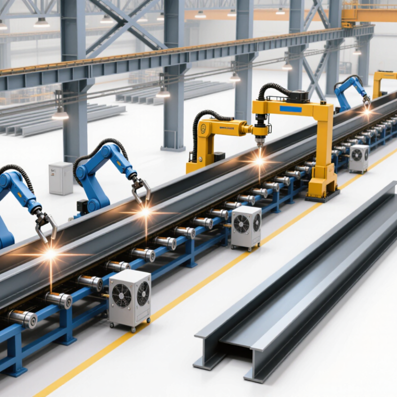
A T-beam welding line is a production system that joins a vertical steel web to one or two horizontal flanges. The finished cross-section resembles the letter T. Typical stations feed and align the plates, tack them in place, then weld the joints continuously. Rollers or clamps hold the web upright while sensors and guides help maintain alignment. Some lines use submerged arc welding, where an arc and granular flux create a steady weld beneath a blanket of material. The exact layout depends on beam size, steel thickness, and required production volume.
Consistency matters. A small gap or tilted web can cause uneven welds and extra straightening work. Operators check fit-up, settings, and weld appearance; automation cannot correct every poor setup. The American Welding Society’s 2020 Welding Workforce Data projected demand for about 360,000 welding professionals in the United States by 2027. That is a workforce estimate, not a T-beam production figure, but it highlights the value of skilled oversight on automated lines. In practice, even a well-adjusted line may need changes when plate dimensions vary. That part is easy to underestimate.
A T-beam welding line is a production system that positions a web plate perpendicular to a flange plate, joins them into a T-shaped section, and checks the finished weldment. The figures below are common illustrative ranges, not universal machine settings; suitable values depend on steel grade, plate dimensions, joint design, and welding procedure.
| Production stage | Equipment or method | What happens | Typical inputs or checks |
|---|---|---|---|
| 1. Plate preparation | Plate cutting and edge preparation | Web and flange plates are cut to the required length and width. Edges are cleaned, and any specified bevel is prepared. | Check plate dimensions, material identification, edge condition, and drawing requirements. |
| 2. T-joint positioning | Web and flange positioning unit with clamps or rollers | The web is placed on the flange centerline, usually at a right angle, and held in position for joining. | Verify web offset, squareness, joint fit-up, and the specified root gap. |
| 3. Tack welding | Manual or mechanized tack welding | Short welds secure the web to the flange and help maintain alignment as the assembly moves to the main welding station. | Tack size, spacing, and placement follow the approved welding procedure and fabrication requirements. |
| 4. Main seam welding | Submerged arc welding (SAW) or another qualified welding process | The two longitudinal joints on either side of the web-to-flange intersection are welded. Mechanized heads and travel systems help maintain consistent torch position and travel. | Current, voltage, travel speed, wire, flux, and weld sequence are set by the qualified welding procedure; there is no single setting suitable for every beam. |
| 5. Straightening | Mechanical or hydraulic straightening equipment, when required | The beam may be corrected for distortion caused by heat input and weld shrinkage. | Measure straightness, flange flatness, and web alignment against the applicable drawing or fabrication tolerance. |
| 6. Finishing and inspection | Cutting, visual inspection, and specified weld testing | The finished beam is cut to length, cleaned as needed, and inspected before release to the next fabrication or coating operation. | Check overall length, profile dimensions, weld appearance, and any required non-destructive testing. |
In short: the line controls plate positioning, joining, and handling to produce a T-shaped member with consistent geometry. Exact process settings and acceptance criteria should come from the approved drawings, welding procedure, and applicable fabrication standards.
A T-beam welding line brings a vertical web and a horizontal flange together, then welds along their joint. Its main components begin with an infeed rack, where steel plates are positioned for assembly. Rollers or a loading device move the parts toward the fit-up station. Here, guides and clamps hold the web upright and keep the flange aligned. Small gaps matter; uneven contact can affect the weld and may pull the beam out of shape.
The welding station contains a power source, wire-feeding equipment, a torch or welding head, and a travel mechanism. The head moves along the seam at a controlled speed while the fixture supports the beam. Some lines weld one side at a time; others use paired heads. A control panel lets operators set parameters and monitor travel. Cooling equipment and fume extraction may also be fitted. Practical details count. Clamps need checking. After welding, rollers carry the beam to an inspection area, where operators look for visible defects and measure straightness. Automation helps repeat the process, but it cannot correct poor fit-up by itself. Heat can still cause distortion, and the best settings may need adjustment for plate thickness and joint condition.
This chart shows a typical sequence of stations in a T-beam welding line, from plate feeding through final inspection. The numbers indicate process order—not cycle time or production capacity. Line layouts and equipment can vary.
A T-beam welding line joins a vertical web plate to a horizontal flange, creating a T-shaped structural member. Its purpose is repeatable alignment and continuous welding, not merely faster production. The sequence starts with cutting and cleaning the plates; mill scale, burrs, or uneven edges can disrupt fit-up.
Then comes positioning. Clamps hold the web perpendicular to the flange, while rollers guide the assembly through the line. Small gaps matter. Tack welds secure the parts before full welding begins.
After tacking, sensors or manual checks confirm alignment and dimensions. Many lines use submerged arc welding to deposit long fillet welds, sometimes on both sides in one pass; equipment and sequence vary by design. Heat can pull the web out of square, so operators monitor distortion and may straighten the beam after welding.
The International Federation of Robotics reported 4.28 million industrial robots operating worldwide in 2023, in its World Robotics 2024 report.
That figure covers all industrial applications, not T-beam lines specifically, but shows the scale of factory automation. In practice, automated travel still needs human judgment: a weld may look smooth while hiding a fit-up problem. Inspect weld continuity, dimensions, and visible defects before the beam moves to finishing.
Common welding methods for T-beam production include submerged arc welding (SAW), gas metal arc welding (GMAW), and flux-cored arc welding (FCAW). SAW is often chosen for long, straight web-to-flange seams. Its submerged arc supports steady, high-deposition welding, but accurate fit-up and suitable fixtures remain essential. GMAW can suit automated or semi-automated lines, especially where consistent travel speed matters. Shielding gas can be disturbed by drafts. FCAW handles heavier sections and some shop conditions well, though the correct wire and shielding approach depend on the job. Manual stick welding is less common for continuous production, but can help with short runs or repairs. Fit-up matters.
The web and flanges are commonly joined with fillet welds. Operators or line controls set the sequence to balance heat on both sides and limit distortion. Clamps keep the web upright, but excessive restraint can create other stresses. Heat still moves. Welding parameters should match the material, thickness, joint design, and qualified procedure. After welding, teams check bead appearance, dimensions, and alignment; additional inspection may be required by the project specification. A fast line can still produce a poor beam if the flange drifts or the weld is inconsistent. No single method wins. The practical choice depends on production volume, access, equipment, and the required weld quality.
Quality control in a T-beam welding line starts before the arc is struck. Operators check flange and web dimensions, edge condition, and material identification. Even a small gap at fit-up can shift the web or create uneven weld penetration. Simple checks matter.
During welding, the line should hold travel speed, torch angle, and heat input within documented ranges. Sensors can flag drift, but operators still need to inspect the seam and respond to changing conditions. A dull or irregular bead may signal poor shielding, contamination, or unstable parameters. It is a clue, not proof. Record the settings and any adjustment beside the beam’s production data.
After welding, visual inspection can reveal undercut, surface cracks, spatter, and inconsistent bead shape. Dimensional checks help confirm straightness and flange alignment, especially after cooling, when distortion may become clearer. Where the inspection plan calls for it, suitable non-destructive testing can examine internal weld areas. Calibrate gauges on schedule, and keep inspection records tied to each production batch. No checklist catches everything. Reviewing recurring defects with welders and line technicians helps refine the process; the review itself can miss patterns if records are incomplete.
Rob was always very honest and upfront about everything and took the time to explain everything I needed.
“highly recommended. They provided us with a great storage container with ontime services.”
“Bought a used container, its perfect, no leaks and in good condition.”
“Good service and prompt delivery. A great option for temporary storage at a decent price.”

Join our mailing list to get the latest storage container inventory and offers